


What Is the Best Traffic VMS LED Display in 2026?
Choosing the best traffic VMS LED display in 2026 is not a brightness contest. It is a roadside performance decision. Drivers may have only seconds to read a message through rain, glare, or passing headlights. A strong display needs clear text, dependable operation, and visibility suited to its location. It also needs to remain serviceable when a component fails. Small details matter.
For this introduction, the following is an illustrative expert perspective, not a verified quotation from a real person: traffic-systems specialist Jordan Lee might put the test this way: “A message board earns its place when drivers can read it quickly and operators can trust it every day.” That principle guides this article’s comparison of traffic VMS LED display options. We will examine pixel pitch, legibility, power use, environmental protection, control systems, and maintenance access. Specifications on paper can look impressive. Real roadside conditions are less tidy. A display that performs well in a showroom may struggle against low winter sun or a film of road dust. There is no single best model for every route. The right choice depends on viewing distance, message needs, installation constraints, and long-term support. This guide offers practical criteria, while recognizing that site-specific testing still matters.
What Is a Traffic VMS LED Display and How Does It Work?
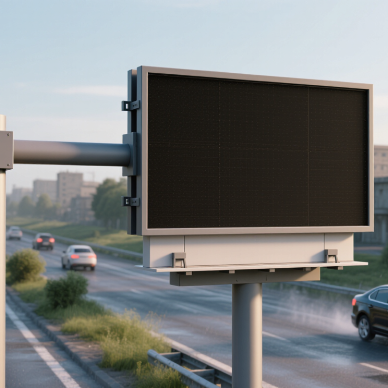
A traffic VMS LED display is an electronic roadside sign that changes its message as traffic conditions change. Its LED pixels form letters, symbols, or simple graphics, while a roadside controller receives approved content from a traffic management center. Operators may update messages manually, or use traffic data from sensors and cameras to support timely changes. Communication links carry the message; the controller checks and renders it on the display. The sign’s brightness adjusts for daylight and darkness, helping keep text visible without unnecessary glare. That matters. NHTSA’s 2022 Traffic Safety Facts report estimated 3,308 deaths in distraction-affected crashes. This does not prove that VMS signs prevent crashes, but it underlines why messages should be quick to read.
A useful VMS combines legible text, strong contrast, dependable communications, and monitoring for failed LEDs or power issues. The FHWA’s 11th Edition MUTCD, published in 2023, provides guidance for changeable message sign operation and message design. In practice, a message should tell drivers what is happening and what action to take, using familiar wording and limited information. For example, “LANE CLOSED AHEAD” is easier to process than a long explanation beside fast-moving traffic. Display size and pixel spacing also matter: drivers need enough viewing distance to read the message before reaching the sign. A technically bright display can still perform poorly if glare, weather, or cramped text reduces readability. There is no single best configuration for every road; agencies should test visibility at actual approach speeds and revisit settings when field conditions change.
| Dimension | How It Works | Typical Specification or Selection Consideration |
|---|---|---|
| Purpose | A Variable Message Sign (VMS) presents changing traffic and road-safety information to drivers. | Used for messages such as lane closures, travel times, incidents, roadwork, weather warnings, and speed advisories. |
| Display technology | An array of light-emitting diodes (LEDs) forms characters, symbols, or graphics. A controller switches the LEDs to create each message. | Choose a full-matrix display when graphics or flexible layouts are needed; character-based displays suit simpler text messages. |
| Message format | The sign converts an approved message into a display pattern, then presents it as fixed text or in successive pages. | Message length, character size, number of lines, and paging should match the road’s viewing distance and available reading time. |
| Brightness and dimming | Light sensors can measure ambient conditions so the controller adjusts LED output between day and night levels. | Outdoor VMS displays commonly use high-brightness LEDs; confirm the required luminance and automatic dimming behavior against local road-authority specifications. |
| Color and contrast | LED color and the sign’s background determine how clearly information stands out in different lighting and weather conditions. | Amber is widely used for changeable traffic messages. Permitted colors and symbol conventions depend on the jurisdiction and sign application. |
| Viewing angle and legibility | LED output must remain readable from the lanes and approach angles where drivers need to see the message. | Set character height and sign placement for the intended viewing distance, road geometry, vehicle speed, and required reading time. |
| Control system | A local or central controller stores, validates, and sends messages to the sign. Operators can select messages manually or through an approved traffic-management system. | Check remote access, permissions, message validation, event logging, and compatibility with the road authority’s existing control system. |
| Communications | Commands and status information travel between the controller and the sign over a wired or wireless connection. | Fiber, Ethernet, cellular, or other links may be used; the appropriate option depends on site coverage, reliability, cybersecurity, and maintenance requirements. |
| Monitoring and diagnostics | Built-in monitoring can report faults such as communication loss, power problems, or LED module failures. | Look for useful fault reporting and remote status checks; monitoring functions vary by system and should be verified in the specification. |
| Weather protection | The enclosure protects electrical and optical components from outdoor exposure. | Specify ingress protection, corrosion resistance, wind loading, and environmental limits for the installation site and applicable local standards. |
| Power and backup | The sign’s power system supplies the LEDs, controller, and communications equipment; some installations include backup power. | Power demand varies with sign size, brightness, message content, and operating conditions. Size the supply and backup to the project’s load and uptime requirements. |
| What makes a VMS the best fit? | Performance depends on how well the display, controller, communications, and installation meet the site’s operational needs. | Prioritize legibility at the required distance, reliable outdoor operation, approved message formats, maintainability, and compliance with the relevant road-authority standards. |
Note: Specifications and permitted message formats vary by country, road authority, and installation. Confirm project requirements with the applicable standards and site design.
