


How to Choose the Right Thermocouple Module for Your Application?
Choosing a Thermocouple Module is not just a matter of matching a sensor plug to a controller. The right choice depends on temperature range, required accuracy, channel count, wiring conditions, and the system receiving the readings. A module in a compact test rig may not suit a factory cabinet exposed to electrical noise. Small details matter.
Lord Kelvin, a pioneer in temperature science and measurement, wrote, “When you can measure what you are speaking about, and express it in numbers, you know something about it.” That principle is useful when comparing modules. Check how each unit handles cold-junction compensation, input isolation, sensor break detection, and calibration. These features can affect whether a reading remains dependable when the room warms, a cable runs beside a motor drive, or one channel loses contact. Specifications deserve a close look.
There is no universal best option. A high channel count may save space, yet it can complicate troubleshooting. A fast sampling rate may sound attractive, but the process itself might change slowly. Sometimes, simpler is better. This guide explains how to match module features to real operating conditions, from thermocouple type and measurement range to communications and mounting. It also points out trade-offs that are easy to overlook. One caution: published accuracy figures do not guarantee the same performance in every installation. Consider the complete measurement chain, then verify the choice against the application before ordering.
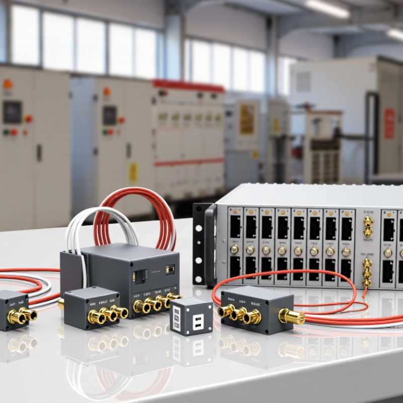
Define the Application’s Temperature Measurement Requirements
Define the measurement before comparing thermocouple modules. Record the normal operating range, expected peaks, and possible cold starts. Measure the real point. A furnace wall, moving part, and liquid pipe can have very different thermal behavior. Note the required accuracy, too, including the sensor’s tolerance and any error introduced by wiring or installation.
Response time matters when temperature changes quickly. A probe inside a thick metal sheath may respond more slowly than an exposed junction. Small details matter. Check how often the module scans each channel, especially when several sensors share one unit. A finer display can look reassuring, but extra resolution cannot correct a poorly placed probe or an unsuitable sensor type. That distinction is easy to miss.
Consider the surroundings where the module will operate. Nearby motors, long cable runs, vibration, and electrical noise may affect readings. Check that the module supports the thermocouple type and temperature range you actually use, along with cold-junction compensation and suitable input isolation. Think through channel count and future expansion, but avoid buying capacity that solves no real problem. Keep notes on the coldest point, hottest point, acceptable error, and desired response time. If those values are uncertain, measure the process under real operating conditions before selecting the module.
