


What Is a Universal Board TV and How Does It Work?
A television can look finished from the outside while one small circuit board determines whether it starts, displays a picture, or responds to a remote. A Universal Board Tv is a replacement control board designed to operate with multiple television models, rather than one exact model alone. It typically processes signals from HDMI and other inputs, runs the television’s software, and sends image and sound instructions to the relevant components. Some kits also combine functions that were separate on the original set. The name sounds broader than the reality. Compatibility still depends on the screen panel, connectors, firmware, and power requirements.
The repair context matters. The Global E-waste Monitor 2024, produced by UNITAR and the International Telecommunication Union, estimates that the world generated 62 million tonnes of electronic waste in 2022; only 22.3% was documented as formally collected and recycled. That figure covers electronics broadly, not televisions alone, but it underlines why repair options deserve careful attention. A universal board may help restore a working set, yet it is not automatically a plug-and-play fix. A mismatched panel setting can produce a blank screen, wrong colors, or no image at all. Not quite universal. This guide explains what the board does, how signals move through it, and which compatibility details matter before choosing one. It also considers the limits: model labels can be incomplete, and a board swap may not solve faults elsewhere in the television.
What a Universal Board TV Is
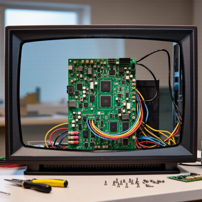
A universal board TV is a television fitted with a replacement control board designed to work across multiple models, rather than one specific set. It is not a universal standard. The board typically processes video and audio, manages inputs such as HDMI, and sends a picture signal to the display panel. Some versions also include a broadcast tuner. The power supply may remain a separate board.
Compatibility depends on details. Check the panel’s resolution, connector type, signal format, and operating voltage before fitting a board. A connector that looks right can still carry a different signal. Firmware and remote-control support matter, too. In practice, a repair technician checks the panel label and board documentation, then tests the set before closing the case. Small mismatches can cause a blank screen or distorted picture. It is easy to overlook one.
The Global E-waste Monitor 2024 reports that the world generated 62 million tonnes of electronic waste in 2022; only 22.3% was formally collected and recycled. That figure does not prove every board replacement prevents waste, but it gives repairability real context. A compatible board may keep a television useful longer. Still, compatibility should be verified—not guessed.
